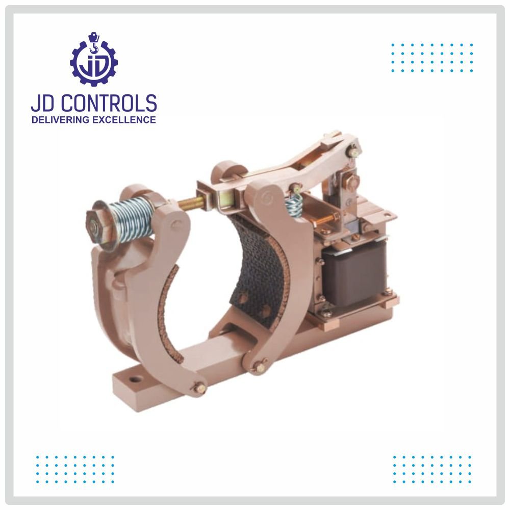
Solenoid operated brake is designed for long life, easy installation minimum maintenance. They are electrically released and spring applied providing ‘Fail Safe’ operation. The retarding torque developed is directly proportional to the spring and pressure.
Constructional Features
Special constructional features such as those listed below account for exceptionally long mechanical life of the brakes.
Prevents link pin breakage and increases the life of the solenoid.
The hardened steel construction of the lever and spring gland reduces wear at the pins and all other points of contact.
The physical properties of the minimize the tendency of the wheel to deposit metal particles in the lining which could result in serious scoring of the wheel.
The tight gripping spring pins insure against the loss of pins due to shock.
Linings attached to shoes by removable flat head groove-pins.
The shoe is actually a part of shoe lever and not separate from it .This makes for fewer mechanical joints and keeps wear points at a minimum.
The solenoid coil can be removed without disturbing the brake adjustment. Solenoid loading is designed to reduce wear.
| MODEL | 4 | 5.5 | 7 |
|---|---|---|---|
| DRUM DIA (MM) | 4” (101.6mm) | 5.5” (139.7mm) | 7” (177.8mm) |
| BREAKING TORQUE (KGM) |
1.36 | 3.4 | 6.8 |
| STROKE (MM) | 25 | 31.4 | 31.4 |
| VOLTAGE IMPUT | 415 | 415 | 415 |
| HOLDING VOLTAGE | 415 | 415 | 415 |
| OPERATING TEMPERATURE | Ambient Temp. | Ambient Temp. | Ambient Temp. |
| COIL | CLASS F Insulation |
CLASS F Insulation |
CLASS F Insulation |
| RATING | Intermittent | Intermittent | Intermittent |
| NO OF OPERATIONS |
720 Operations/Hr | 720 Operations/Hr | 720 Operations/Hr |
| TOTAL WEIGHT (KG) |
5.5 Kg | 11.5 Kg | 15.5 Kg |
The method most generally used to determine the required braking torque is to calculate the full load motor torque by means of the following formula:
T =
T = Full load motor torque in Newton Metre (Nm)
kW = Motor output in Kilowatts
n = Rated speed of the motor shaft on which brake wheel is mounted in revolution per minute(r.p.m)
The torque rating of brake selected should be at least equal to the full load motor torque for the duty considered.
| BRAKE TYPE |
DRUM DIA | TORQUE MAX | ||
|---|---|---|---|---|
| INCH | MM | KGM | NM | |
| 4 | 04 | 100 | 1.3 | 13.6 |
| 5.5 | 5.5 | 139.7 | 3.4 | 34 |
| 7 | 07 | 177.8 | 6.8 | 68 |